AE-390
CONCRETE FRAME
GROUP 9
types of concrete construction
These figures and tables will help illustrate if Concrete Frame construction is a suitable material for the intended structure. Below an outline is given for some of the properties a typical concrete frame can support, such as the span lenght as well as column and girder sizes. The different method of sitecast concrete slabs AND GIRDERS are illustrated with both conventional reinforcing method as well as post tensioning design.
Formed Concrete


Figure T1: Sitecast Concrete Slabs
FIgure T1, above shows the span that a sitecast concrete slab can support given the type of construction, which can be shown next to each chart. Each type of construction is applicable under conditions and have various depth of slab to to span ratios which can be seen individually for each type from its chart. They are separated into post-tensioning consturction and conventional reinforcing methods.


Figure T2: Sitecast Concrete Joist
Figure T2 shows the different beams and girders and their span as well as thickness associated with each for the each of the different construction methods, conventional reinforing and post tensioning, as well as one-way joints, to the left, and joist bands on the right.
Columns
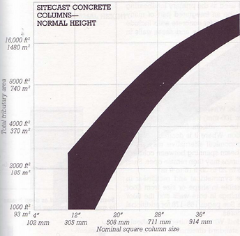


Figure T3: Sitecast Concrete Columns
The charts in figure T3 above illustrate column sizes for 12 foot height and above. The chart to the right shows the tributary area versus the nominal square column size while the chart to the left is for unbraced column sizes above 12 feet and the corresponding column size to accomodate.
Walls


Figure T4: Sitecast Concrete Walls
Figure T4, to the right, shows the total loaded width of sitecast concrete wall construction for different thicknesses. To the right is to show the height of sitecast concrete wall against their thickness for both loadbearing and non loadbearing applications.
precast Concrete


Figure T5: Precast Slab
Figure T5 shows precast concrete and the span that slab of different depths are able to reach To the right side of the chart it also shows where hollow core slab and solid slabs overlap slightly and find their own points of usage.
Beams/Girders


Figure T6: Precast Girder/Beams
Figure T6 is given in order to show the beams and girder span that precast concrete can accomodate the two different charts illustrate the separate types of construction that can exist. To the left si for beams of the variety show at the far left. The chart to the right is for T span girders and also illustrates the ranges that each can reach.
Columns


Figure T7: Precast Colums
Figure T7 to the right shows column of normal height up to 12 feet and the square column size needed for the tributary area above. To the right is a chart showing for column above the normal 12 foot height and the column size required for each rise in height by 4 foot increments.
Walls


Figure T8: Precast Walls
Figure T8 is given to illustate the depth required for precast concrete wall construction. To the left is given for normal precast walls for both prestressed and conventional reinforcing methods and to the far left is a picture showing this type of structure. To the right is a chart for precast concrete wall construction for ribbed wall panels which are shown in a picture to the far right.