AE-390
CONCRETE FRAME
GROUP 9
Connections
Connections for different applications of concrete can accomodate almost any type of material interface. Some of the common types found in most buildings are outlined below. They are seperated into two types of concrete frames, formed concrete and pre-cast concrete. Within these subsets are developed and outline the method of connnections for one to another.
Formed Concrete
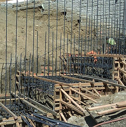
Figure C1: Rebar Foundation

Figure C2: Concrete Pier Foudations
Concrete foundations are the base of any structure. A foundation is responsible not only for transmitting the loads of the structure to the subsurface but connecting the different elements as well. Connections come in all varities and vary methods as well. The most common is using reinforcement bar to provide unity between the separate elements, an example of this can be seen in Figure C1. Anothe r application is building pier column out of concrete and connecting the successive levels to them, transmitting the load to a solid subsurface, this method is shown in figure C2.
As for as the foundation soil interface it is rests directly on the soil and kept in place by gravity. This is why it is important for the concrete to be in contact with bedrock or a suitable substrate.

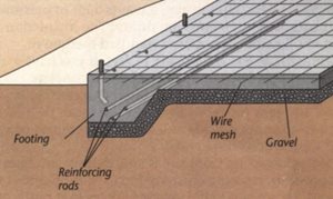
Figure C3: Concrete Slab Floor
Figure C4: Slab on Soil
Slabs consist of the floors and ceiling within a building and are connected to the beams and columns using suitable connectors such as rebar or other types of fasteners which vary due to application. Often times a steel slab will be integrated as with a steel to form the floor of a building while the rest of the structure consists of steel this is shown in figure C3, to the left.
fIf the slab is to be in direct contact with the soil a crushed stone bed is layed below to prevent cracking and allow for water to drain under the structure, this is illustrated in figure C4.

Figure C5: Beam/Column Forms

Poured concrete beams and colums use a simialr method of connection as illustrated above with a network of reinforcing bar serving as a bond between the different components, formwork for this type of application can be seen in figure C5, which shows the cast for the concrete to be formed.
Beams and columns are constructed one level at a time with reinforcing bars stemming from the previous layer to the next in order to unite each section as a whole, an example of this is shown in the vertical columns figure C6
Figure C6: Concrete Column Connectors

Figure C7: Wall Connecting System

Poured concrete walls are attached using a similar construction method integrating steel reinforing bar to create a joining structure where the wall connects to the with the adjaent parts of the building, an example is shown to the left in figure C7. Similar to the columns a stem of reinforcing bars or anchors are left exposed in order to tie the next section together.
Some methods of construction call for different material to attach to concrete in which case an anchor is left exposed in order to fasten the material securely.
Figure C8: Wall Anchors
Pre-Cast Concrete

Pre cast concrete slabs incorporate a similar method of attaching sections as formed concrete. Since precast is engineered to specifications anchors can be placed within the section during manufacturing in order to connect the components in the field. These anchors vary drastically given the application and requirements of design but usually incorporate bolted connections. The method of connecting on site includes placing the panel in its designated postion and tightening the connecting bolts. A Slab being lowered into place is shown to the left in figure C9.
Figure C9: Precast Slabs
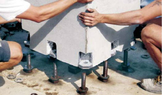
Pre-cast columns use anchoring bolts placed into the piece to be connected, these are usually set ahead of time to dimensions specified by the pre-fabricated member. After aligning the column and setting it in large bolts are sectured and used to plumb and fix the column permanently, this process is illustrated in figuer C10 shown to the left. On its own the column is stable but the most strenghth gain is experienced when the interconnection of beams and columns is completed.
Figure C10: Precast Column Connection

Figure C8: Wall Anchors

Figure C8: Wall Anchors
Horizontal beams use a slightly different method of connecting to the columns. The method of construction includes lowering the beam down onto a support fixed to column. Gravity seats this connection between the members while a bolted attachment is used to ensure no lateral moverment is experienced. This method of connecting can be seen in figures C11 and C12 as seen to the left.
Figure C11: Precast Beam Family
Figure C12: Beam/Column Connectors


Figure C10: Precast to poured connection
Figure C10: Bolted Wall to STeel connector
Precast concrete wall are developed with all types of methods for attachment depending on the specific application. They are usually attached to foundation and complete an engineered specification, The floor can be connected to the walls within a structrue by using reiforcement bar as shown in figure C13. The walls are built to engineered specifications and come in sections, similar to the other applications for precast concrete they are bolted to one using anchors placed during fabrication, an example of this is seen in figure C14 to the left. Like columns these require hoizontal bracing during construction since they don't resist lateral movement without the other components of the structure as well.